For This Project We are going to use the pervious circuit (see the LED light bar tutorial) to build on top off. We don’t need to change it at all, we are just going to add to it and write some new code. What we are going to make is an LED bar graph. The kind of LED display used to give feedback for things like volume control on a speaker system. For us, we are simply going to use a Potentiometer to increase and decrease the number of LED’s turned on.
Components required:
- Arduino board
- Breadboard
- Wires
- 8 x 220 Ω resistors
- 8 x LEDs
- Potentiometer - this and 3 extra cables are the only additions to the pervious tutorial component list
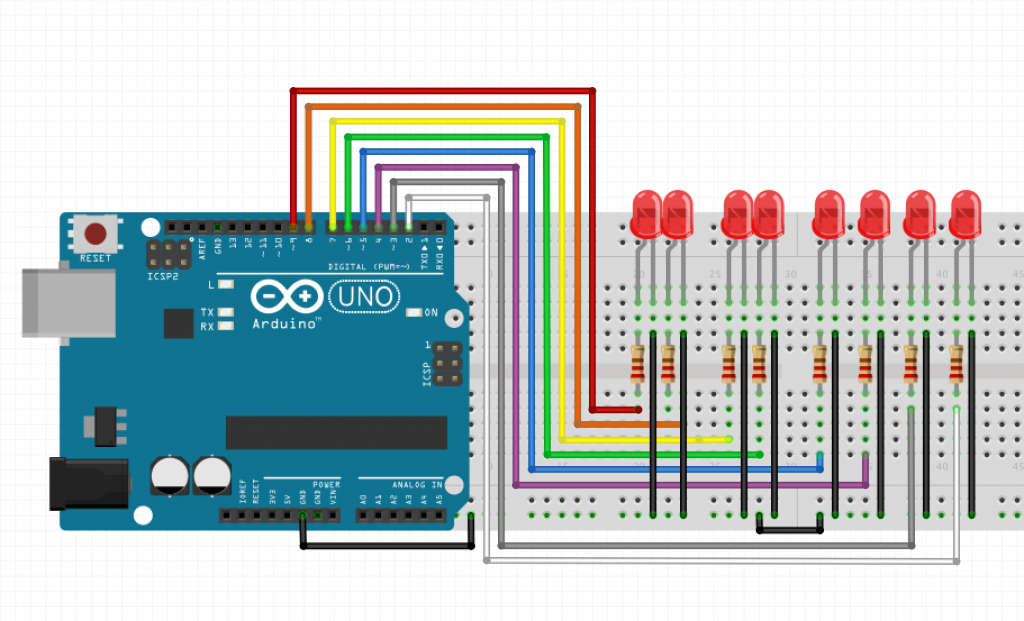
So here is the original circuit from the LED light bar tutorial.
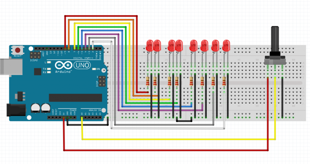
Now we add in the Potentiometer.
If thats a little overwhelming, here is the potentiometer circuit on its own.
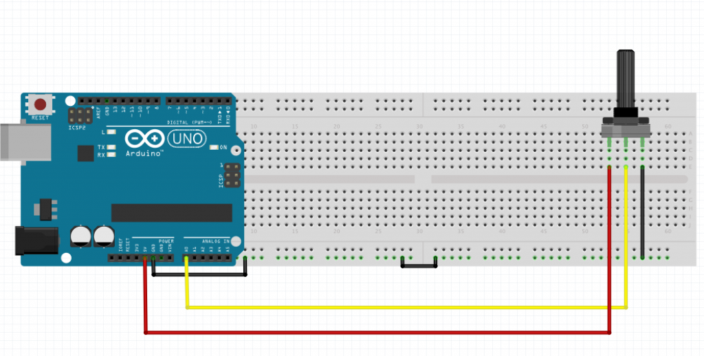
That’s not so complex at all.
The potentiometer acts as a voltage divider, which basically means that the voltage seen on the middle pin will be somewhere between the voltage levels applied to the other two pins. You can change the voltage on the middle pin by turning the knob, but it will never go outside the bounds of the voltages on the other two pins. In the circuit above, it means that we can turn the knob on the potentiometer to get any voltage between 0V and 5V on the middle pin. This pin is then connected to our analog input (A0 on the Arduino board). The Arduino reads the voltage level and performs an Analog to Digital Conversion (ADC), i.e. it changes the voltage to a number between 0 and 1023. This is just a simple scale to represent voltage level where 0 = 0V and 1023 = 5V.
The biggest change from the LED Light bar is the code we use. Create a new Sketch and add the following:
[c]
//Define which analog input used for potentiometer
const int potentiometer = A0;
//number of LEDs in our array
const int numberOfLEDs = 8;
// digital pins corresponding to our LED circuits
int leds[] = {2,3,4,5,6,7,8,9};
void setup(){
// loop through our digital pins to set them to Output
for(int i =0; i < numberOfLEDs; i++){
pinMode(leds[i], OUTPUT);
}
}
void loop(){
// take a reading from the potentiometer
int reading = analogRead(potentiometer);
// for an explanation of the map function, see below
int level = map(reading, 0, 1023, 0, numberOfLEDs);
for(int i = 0; i < numberOfLEDs; i++){
if(i < level){
digitalWrite(leds[i], HIGH);
} else {
digitalWrite(leds[i], LOW);
}
}
}
[/c]
The map function takes five parameters used to map a value in one scale range to another scale. We are looking to map each LED 8 steps as values between 0 & 1023 (because this is the range of readings the Analog input can read).
The Map() function’s five parameters are:
- The current value we wish to map to a particular scale
- The fromLow value which set’s the minimum value of the scale we are mapping from, in our case the minimum value that can be read from the analog pin A0 i.e. 0
- The fromHigh, which is the maximum value for the scale we a mapping from, 1023 in our case
- The toLow which is 0 in our case as we will have 0 LED lighting when the reading is 0
- The toHigh which is 8 in this example as we want all our LED’s lighting when the potentiometer is turned up to full
Now plug upload the code to the Arduino and you should have the result shown below.
This Tutorial is based on a post on my own blog.