API Month Day 1 - Citymapper

So day one has arrived, if you are curious as to what I’m talking about have a look here. So I have to decide every day if I am going to cycle to work or take my local train. Lots of info helps me make this decision.

How long will the train take?

Will it rain?

How hungover am I?

Now API’s can’t help with the last one (although google now is getting pretty close to being able to guess) but it can help with the first two. To start today I thought I would start with a really simple one, how long will it take to get to work by train?

This can very variable. I have to change from train to tube and then change tube too to get to work. It’s a pain. So hence why I check. So I wrote this simple program, Train.py, to check to see my estimated commuting time to work. As my bike commute is a pretty predictable 44-48 minutes i can then make a decision.

This is a simple piece of code but I’ll describe what you need to use an API and the practicalities around using it in python and manipulating its output.

Lets start with the Citymapper API itself. It’s very straightforward:

  • Head here to register for an account and an API key.

  • Head here to check out the API documentation.

You can use the documentation page to do a sample push and get an idea of the form of a request. I use a chrome extension called postman to check my calls and responses to make sure I have everything right before I start programming. So as an example to check the API to see travel time between two points you would call:

https://developer.citymapper.com/api/1/traveltime/?startcoord=51.2688199%2C-0.1783686&endcoord=51.560117%2C-0.0722408&time_type=arrival&key=[INSERT KEY]

So its pretty human readable, to go through it, you are checking the Citymapper mapper API server for a travel time. Then after the ? you can specify a list of parameters, the order doesn’t matter but there are required inputs. You can see above I specify start location, end location, arrival time and my key.

I obviously haven’t included my own key but if you were to put your own key there and put that whole message into POSTMAN or your browser you would see the following response.

1
{ "travel_time_minutes": 54, "diagnostic": {"milliseconds": 2907} }

Again this is in a lovely human readable JSON (Just Simple Ordinary Notation) format. If we were to do some JSON parsing we could pull out the ‘54’ minutes variable and we’d have our answer.

So how do I program this? I use python for all my programming needs so I’ll discuss this now. The requests library is your friend so if you don’t have it installed pop over to your favourite terminal window and run:

sudo easy_install requests

Once that is installed, you can run the following python program to print out on the command line what we just ran in a browser window.

1
2
3
4
5
6
7
8
9
10
11
12
# -*- coding: utf-8 -*-
# Program to check how long it will take me to get to work
# Greg Jackson 1st dev 2015
# Twitter @gr3gario or github gregario
# Day one of the Month of API
import requests
import json
url = "https://developer.citymapper.com/api/1/traveltime/"
payload = {'startcoord': '51.4618199,-0.1793686', 'endcoord': '51.560117,-0.0722408','time_type':'arrival','key':'INSERTKEY'}
r = requests.get(url, params=payload).json()

Output looks like this:

1
{ "travel_time_minutes: 54, "diagnostic": { "milliseconds": 2907} }

Look familiar? Yes? Great. If you use the following code you will just return 54.

1
2
3
r = requests.get("https://developer.citymapper.com/api/1/traveltime/?startcoord=51.2188199%2C-0.1013686&endcoord=51.560117%2C-0.0722408&time_type=arrival&key=[INSERTKEYHERE]").json()
print(r['travel_time_minutes'])

There you go. If you want to play with JSON more have a look at this tutorial here. I found it super helpful. Finally I want to make this a little more user friendly by including the payload as a separate variable. This way you can make changes easily or include this as a function in a larger program or load the start/end coordinates from a file.

1
2
3
4
5
6
7
url = “https://developer.citymapper.com/api/1/traveltime/”
payload = {'startcoord': '51.4618199,-0.1793686', 'endcoord': '51.560117,-0.0722408′,'time_type':'arrival','key':'INSERTKEYHERE'}
r = requests.get(url, params=payload).json()
print(r['travel_time_minutes'])

So that’s me, day one was pretty simple but this is a learning experience for me. I haven’t played with a lot of these simple programming methods before so I’m learning as I go. My code is up on Github here if you want to play.

I got curious to see how much this commuting time varied over the course of a day. So I wrote another program TrainLoop.py that ran forever, checking once every 90 seconds and piping out a file that I can plot tomorrow. Why 90 seconds you ask? There’s a 1000 call limit per day on the free API for Citymapper. 24 hours / 1000 is a API call every 86 seconds.

Tomorrow I’ll look at a weather service to find out will it rain and if it will rain during the day. Could be useful for a comparison. Should be fun 🙂

API Month

I do a lot of tinkering with API’s for work. They make operating with other people’s systems super simple and for IoT, an open API is often touted as an easy way for third parties to use your data for monitization purposes, like Intel’s Mashery, or as a public service with TFL (transport for London).

I just threw out a lot of acronyms so very quickly, what are API’s?

Application Programming Interfaces are a way of accessing or controlling a third party system with a well documented set of commands. A good programmer builds in such capabilities into their product so it can be used easily by others wanting to implement/build upon their work. A good example of this is Google Maps API was used to build Citymapper, a fantastic mapping service that is now in dozens of cities around the world. It takes google’s data and mushes it together (the technical term would be data fusion but I prefer “mushes together”) with other local data sources for traffic/transport/weather to make a better mapping service.

And what is IoT?

IoT is the Internet of Things, its so hot right now… Simply, its about making dumb objects smart. Fridge becomes Smart Fridge. To become smart it needs to sense its environment in order to make its own decisions. Sensing the environment creates a bunch of data about said environment. API’s let you easily access said data.

Anywho, I just thought that it would be a cool idea to have an API month. Every day I will create a simple app to do something using an API at its core. It will definitely be simple and most probably be written in python. It may have a physical implementation depending on how busy I am but it will definitely pull some data from a service for some silly/informative/instructional purpose.

Tomorrow will be day one. I’m going to start with an easy one. I decide each morning if I should cycle or take the train to work in London. The train is super variable every as I have to go train to tube to another tube to get to work. If any of them are down or have delays its takes forever. So I thought I could write a script that automatically check to see how long my commute will be.

Hour of code

The Gaelscoil Thulach na nÓg were a great success last week. Students and facilitators alike had great fun. Students learnt and taught each other a great deal about coding and produced wonderful festive greeting cards.

Originally the plan by Pól, Bernie and Fiona - the session facilitators - was to introduce the students to coding via the Scratch.

Some of the inspiring creations exhibited included: Santa bouncing on a trampoline - presents flying out of his sack - as he bid the viewer “Ho! Ho! Ho! Merry Christmas”, Ice skating reindeer and Dublin City sleigh rides.

Hopefully we will be back gain soon to build on those sessions, maybe adding Arduino Scratch elements to the amazing greeting cards already created.

Nollaig Shona!

IMAG0704_BURST002

An LED Bar Graph

For This Project We are going to use the pervious circuit (see the LED light bar tutorial) to build on top off. We don’t need to change it at all, we are just going to add to it and write some new code. What we are going to make is an LED bar graph. The kind of LED display used to give feedback for things like volume control on a speaker system. For us, we are simply going to use a Potentiometer to increase and decrease the number of LED’s turned on.

Components required:

    1. Arduino board
    1. Breadboard
    1. Wires
    1. 8 x 220 Ω resistors
    1. 8 x LEDs
  • Potentiometer - this and 3 extra cables are the only additions to the pervious tutorial component list

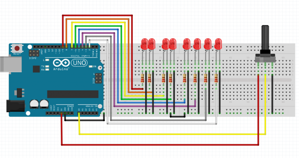
So here is the original circuit from the LED light bar tutorial.

full LED Light Bar circuit

Now we add in the Potentiometer.

led bar graph

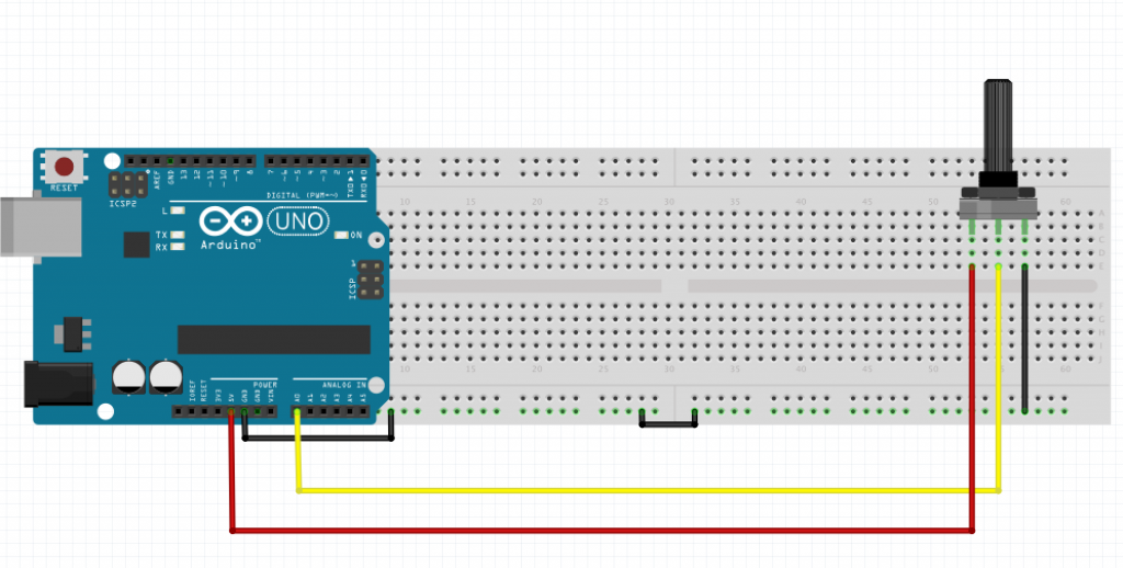
If thats a little overwhelming, here is the potentiometer circuit on its own.

potentiometer

That’s not so complex at all.

The potentiometer acts as a voltage divider, which basically means that the voltage seen on the middle pin will be somewhere between the voltage levels applied to the other two pins. You can change the voltage on the middle pin by turning the knob, but it will never go outside the bounds of the voltages on the other two pins. In the circuit above, it means that we can turn the knob on the potentiometer to get any voltage between 0V and 5V on the middle pin. This pin is then connected to our analog input (A0 on the Arduino board). The Arduino reads the voltage level and performs an Analog to Digital Conversion (ADC), i.e. it changes the voltage to a number between 0 and 1023. This is just a simple scale to represent voltage level where 0 = 0V and 1023 = 5V.

The biggest change from the LED Light bar is the code we use. Create a new Sketch and add the following:

[c]

//Define which analog input used for potentiometer

const int potentiometer = A0;

//number of LEDs in our array

const int numberOfLEDs = 8;

// digital pins corresponding to our LED circuits

int leds[] = {2,3,4,5,6,7,8,9};

void setup(){

// loop through our digital pins to set them to Output

for(int i =0; i < numberOfLEDs; i++){

pinMode(leds[i], OUTPUT);

}

}

void loop(){

// take a reading from the potentiometer

int reading = analogRead(potentiometer);

// for an explanation of the map function, see below

int level = map(reading, 0, 1023, 0, numberOfLEDs);

for(int i = 0; i < numberOfLEDs; i++){

if(i < level){

digitalWrite(leds[i], HIGH);

} else {

digitalWrite(leds[i], LOW);

}

}

}

[/c]

The map function takes five parameters used to map a value in one scale range to another scale. We are looking to map each LED 8 steps as values between 0 & 1023 (because this is the range of readings the Analog input can read).

The Map() function’s five parameters are:

  • The current value we wish to map to a particular scale
  • The fromLow value which set’s the minimum value of the scale we are mapping from, in our case the minimum value that can be read from the analog pin A0 i.e. 0
  • The fromHigh, which is the maximum value for the scale we a mapping from, 1023 in our case
  • The toLow which is 0 in our case as we will have 0 LED lighting when the reading is 0
  • The toHigh which is 8 in this example as we want all our LED’s lighting when the potentiometer is turned up to full

Now plug upload the code to the Arduino and you should have the result shown below.

This Tutorial is based on a post on my own blog.

An LED Light Bar

For the second project in our Beginning Arduino series I decided to build an LED Light Bar (think of Knight Rider). This will teach us some of the basics of working with multiple outputs and it will allow us to build things like Christmas light decorations. We will also gain a good foundation for working with a 7 Segment LED which we will look at in a later date.

What we need:

    1. Arduino board
    1. Breadboard
    1. Wires
    1. 8 x 220 Ω resistors
    1. 8 x LEDs

It isn’t essential to have 8 LEDS/Resistors, you can have less or more you just need to have a resistor for each LED and a digital out on the Arduino.

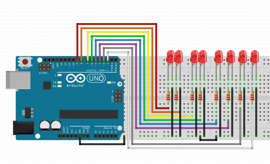
Put all the components together as shown in the image below

full LED Light Bar circuit

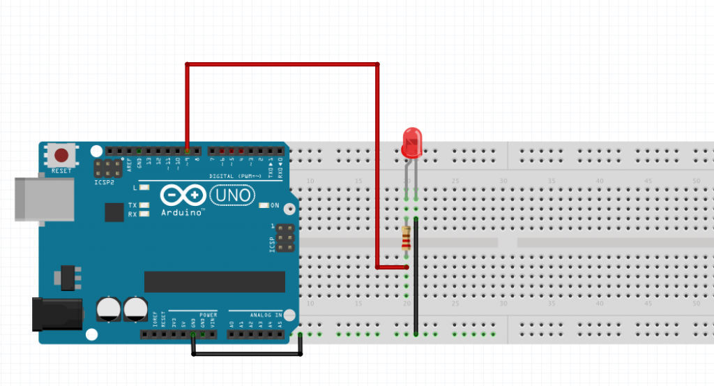
In case that circuit is a little overwhelming here is a circuit with just a single LED wired up. All the other LED’s follow the same layout but with their input from a different digital out on the Arduino.

single circuit

Now fire up the Arduino IDE and create a new sketch with the following code:

[c]

void setup(){

//looping through the digital pins 2-9

//and setting the mode to output

for(int i= 2;i <= 9;i++){

pinMode(i, OUTPUT);

}

}

// Simple function to loop through all LEDs to turn them off

void turnLEDsOff(){

for(int i= 2;i <= 9;i++){

digitalWrite(i, LOW);

// wait 200ms

delay(200);

}

}

//main loop

void loop(){

// move through the LEDs lighting single led at time

for(int i= 2;i <= 9;i++){

//turn off All LEDs

turnLEDsOff();

// turn on single LED @ position i

digitalWrite(i, HIGH);

// wait 200ms

delay(200);

}

// same as above but in reverse order

for(int i= 2;i <= 9;i++){

//turn off All LEDs

turnLEDsOff();

// turn on single LED @ position i

digitalWrite(i, HIGH);

// wait 200ms

delay(200);

}

}

[/c]

Plug in the Arduino to a power supply and There you have it, an LED Light bar.

Issues I experienced

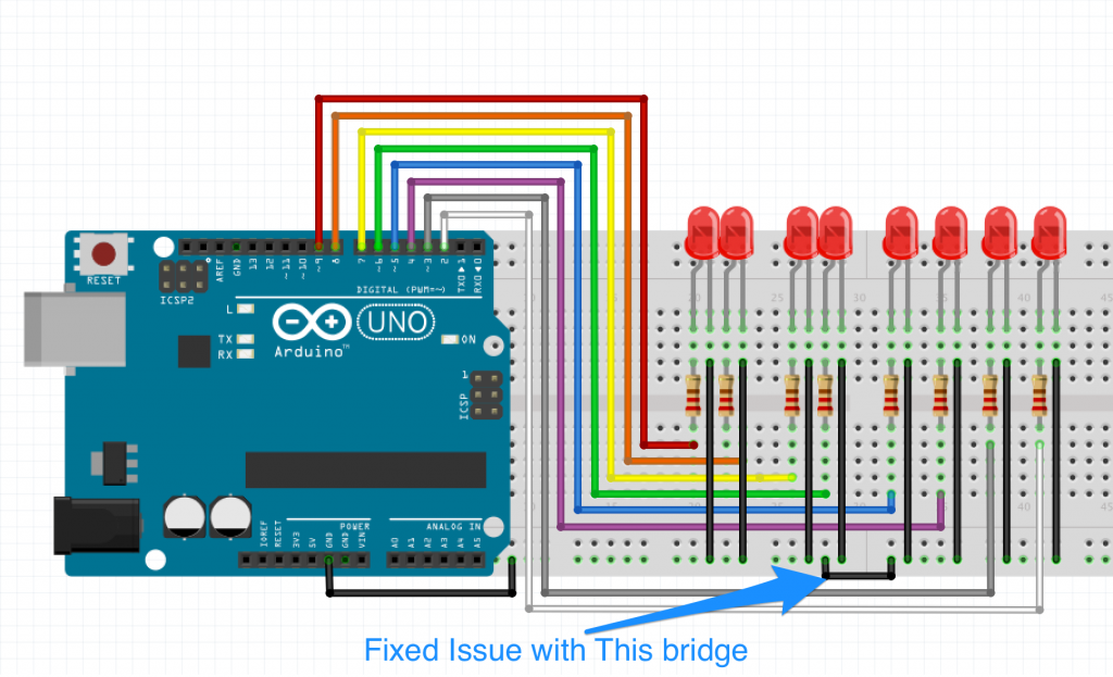
While doing this project I came across an issue where the last LED would not light up for me. I tried swapping LED’s, resistors and cables but found nothing was faulty. Could the breadboard of been faulty? Sort of, but not really. I basically didn’t realise the was a break in the ground rail on the bottom. So I had to bridge the break ( see the image below).

full circuit with bridge fix

But Why did the other LEDs on the same side of the break work? Because when an IO pin is configured as an OUTPUT, and is set LOW, it is effectively connected to ground, allowing the rest of the circuit to behave as normal

Here is a video show this issue:

I based this tutorial on a post I wrote for my own blog and on the LED Light Bar project in Arduino Project Handbook

Retro GameBox Kit

Project files: Google Drive

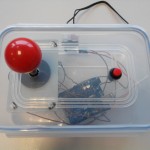
A while ago we ran a workshop in Rua Red, where the participants built their own Arduino-powered Retro games console. It was a great success; all the consoles worked and we all got a little bit better at Space Invaders, Parachutes, Asteroids and Sudoku.

In preparation for that workshop, I put in a good bit of work sourcing parts cheaply both online and locally. On top of that, we all chipped in with making up an instruction document, getting the tools we’d need together and checking that stuff actually worked. When the workshop went off so well, we got to thinking that it’d make for a really nice kit. Especially since all the hard kit preparation work was already done!

GameBox

Lunch Box Case

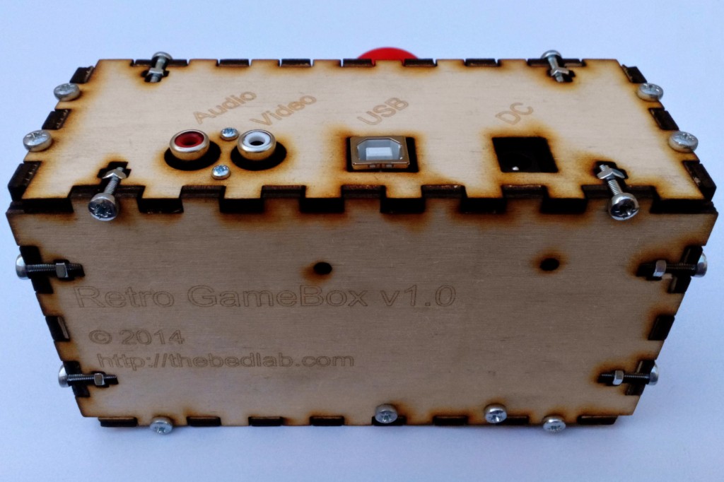
One remaining task for packaging the Retro GameBox up into kit form was the project’s enclosure. You may remember that we were using lunch boxes on the night as our console cases. Well, I recently started playing around with laser cutting, so did up a quick enclosure using http://www.makercase.com/ and added in all the mounting holes for the hardware with Inkscape.

The design files (available in the Project files link at top) are still a little rough and will definitely be improved in the future but I’m pretty happy with this as a starting point! It was made with 4mm Birch Plywood Moisture Resistant BB/BB(MR) from woodworkers.ie. We decided to go down the wood route because you really can’t get much more retro than that.

RGB-Profile

Among the changes I’d like to make are:

  • Change the box design from T-Slot to Finger joints for everything but the top face, so that we can save on nuts/bolts
    • Means we’ll need some corner pads on the bottom so that it sits on a level surface with no wobbles
  • Our logo didn’t come out in the final DXF file, so we’d need to fix that
  • Maybe some branding on the top face too

Once the design has been fixed up, we’ll get it up on thingiverse and also release the project as a kit. Feel free to comment below if you’d be interested in the kits or have any feedback/suggestions for us. Who knows, maybe this time next year we’ll be showing it on the Late Late Toy Show!

BattleShots

So I made a game…

Build1

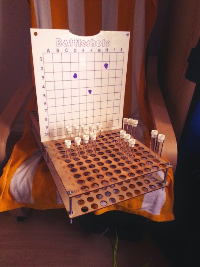
Battleshots has been born… Its a drinking game based on battleships. You get 5 ships, 1X5 test tubes, 1X4, 2X3 and 1X2 test tubes. Fill those tubes with a responsible level of the alcohol of your choice. The aim of the game is to sink all your buddies ships before they sink yours! And there’s drinking. You get hit and you take a shot… ALL the fun. Anywho… Proof of the fun can be found here:

I’ve made some changes from the above to make everything symmetrical and the board wider as the slot for the upright piece in the above photo was very close to the edge and could easily break. I’ve put the files on thingiverse for anyone wanting a go: http://www.thingiverse.com/thing:561822

The design is pretty straightforward and the link covers the basics of how to put it together. In terms of assembly I thought I’d talk through some of the design. Firstly you’ll need:

  • 1* 600*400mm sheet of 3mm white acrylic
  • 2* 600*400mm sheets of 3mm laserply
  • 8* 120mm carraige bolts (M6 I think…) and 24 nuts to do the gaps (or some tubing cut to length… that would be neater)
  • A purple whiteboard marker
  • Test Tubes: http://www.amazon.co.uk/dp/B005ZR5S8W/ You need 40 to have a couple of spares so 60 may be overkill
  • A laser cutter

The whole thing cost around £30 (sans the lasercutter) but I think it could be done for 20-25 if you find a cheap supplier for the test tubes. Anywho I thought I would talk through providing contrast on lasercut acrylic. I thought the purple on white came out really well and was very simple to do.

Capture

Its very straightforward. Just engrave on the material and then highlight the crap out of it. Use a whiteboard marker rather than a permanent marker. In the third photo above you can see one pass. If you clean it off with a papertowel and do a couple of passes you will have a similar output to the final photo… Neat, eh?

I have since seen acrylic paint on solid engravings on transparent acrylic which looks lovely too and I must try out in the future!

Edison as an IoT Device

Introduction to Edison

Introduction to Edison

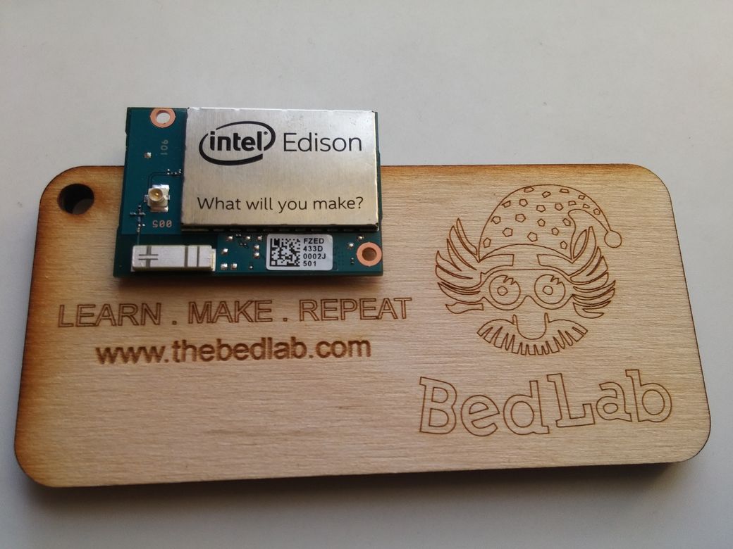
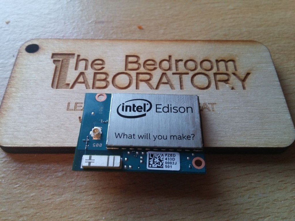
I’ve been playing with the Edison that I got at the hardware hackathon BedLab attended a few weeks back. Thanks to the guys from Intel for donating a few to the BedLab fund. (Full disclosure on the post, I work for Intel over in London (http://www.cities.io so I’ll try to keep the gushing praise to a minimum)

20141124_155131

Its pretty cool, out of the box its a lot more functional than the Gen one Intel Galileo and was pretty easy to get updated and up and running. I won’t go into the detail of setting it up as there was a pretty straightforward step by step guide for doing it. Broadly the steps are:

  • Install FTDI driver for the board
  • Install Arduino IDE with Intel addon
  • Install Edison drivers

Being on the internal trial for the Edison pre release they did a good job of integrating all the tools into one installer in order to talk to and work with the board.

The drivers in particular are cool, they let you:

  • connect to the device over serial (using putty to access the linux side of things),
  • Transfer Arduino scripts if you want to program it via Arduino
  • Access the storage on the Edison as an external drive

So pretty functional. Anywho links are here…

Getting started: https://communities.intel.com/docs/DOC-23147.

The one quirk I’ll say is that you need two USB’s to connect to a computer to do the programming, which is a little cumbersome.I set mine up and connected it to my home wifi and then just SSH’ed into it, this is where you should be at once you complete the above getting started guide.

Some other handy things to know when playing with the device. You are not limited to Yocto, the native Linux distro that comes with the board. If you like to work through Python or Node you can use their package managers to get most things working. Working with Yocto itself can be challenging for the hobbyist. There’s no apt-get for instance, which is a bit of a pain. Yocto was designed to be for robust embedded applications. Its designed to be made from source for a specific application. Its a barebones version of linux where you only load the parts of the stack you need for your application. The theory holds that the less stuff on the build the less can go wrong and the more robust your system will be.

So if you want to make a smart thermostat you can only load the systems you need, if you want to prototype something though it can take 4 hours to add that new wifi driver and build the system again from source. If you want to play with Debian on the board Emutex have released a debian build at emutexlabs.com

The next handy thing is accessing the edison as an external hard drive. You can plug it in and transfer over any files you want. SCP also works if you want to go down that route but if you want to transfer big files or pass information via a PC easily this is a nice trick. Found the inspiration here: https://communities.intel.com/thread/55510. Once you’ve transferred your files from the PC to the edison, the next step is to mount the drive on the Edison itself.

1
2
3
4
5
6
7
8
9
10
11
12
13
14
15
16
rmmod g_multi
mkdir /update
losetup -o 8192 /dev/loop0 /dev/disk/by-partlabel/update
mount /dev/loop0 /update
```
Then if you want to reverse the process:
```bash
cd /
modprobe g_multi
umount /update
then pull the usb cable and re-insert it, at which stage the disk should re-appear on your host machine.

Finally there’s been some nice benchmarking done by David Hunt (He also has made some pretty cool photography hacks, its worth checking out his work)

Cloud Infrastructures

The Edison is pitched as an enabler of the internet of things (IoT) so I thought I would talk a little bit about using the Edison as a platform for sensors. There are lots of cloud based infrastructures that one can use to send data from these devices. I’m going to stick to the Linux side of things as I’m used to operating in that environment rather than through the arduino cross compiler.

There’s actually an IoT development kit baked into the Edison, it posts to an intel backend. It seemed quick to setup, I had a bit of a play of a Monday evening to see what its like. There’s a tutorial here if you’re interested. There’s a node and C version depending on preference. In an hour or so I had an account setup and the device associated with its backend sending a virtual sensor reading. Can’t speak to its scalability/feature set but it had a shallow learning curve at the very least.

Another option is to build your own cloud storage system. At Bedlab this is becoming a bit of a specialty with with a bunch of different types of IoT style systems with various time series datastore types being made and even (feel free to correct me here guys) 3 RESTful API’s being built at this stage for various projects. Check out the following for more info:

There’s other online based systems that can quickly be setup to do the heavy lifting for your IoT device. I’ve had a play with GERAS from the guys over at www.1248.io, its quite good, doing exactly what you need it to, reminiscent of the old Pachube system. Xively is probably the best known system. Formerly Cosm, Formerly Pachube… Its so good they named it trice. Anywho, how I’ve finished kludgening that previous sentence into my post lets wrap up. I’ll write a follow up post on playing with the Edison over Xively. Stay tuned for more .

Turning on an LED from a Button

So you want to Learn to program and build projects with Arduino. Me too, and I want to help you learn from my experience, as I too am a beginner.

I could do the boring, pointless Arduino version of Hello Wold, Blink!, tutorial that most people start with, but it doesn’t involve enough as far as I am concerned ( it’s all already done for you), but go ahead if you feel its worth it. For me, I want to be able to interact with it.

So for my first Arduino project I want to press a button to turn on an LED. This involves 2 Arduino Fundamentals, reading input (the button), processing it in our program (an Arduino sketch) and output a result ( turning on or off an L.E.D.).

so without boring you, lets Jump straight in…

Components we need:

  • Arduino
  • Breadboard
  • Wires
  • LED
  • Push Button
  • 1 x 10k Ω Resistor
  • 1 x 220 Ω

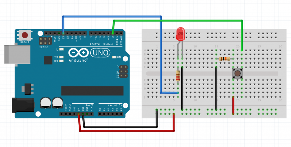
First I Followed the Tutorial in Arduino Project Handbook by setting up my circuit as in the image below:

Push Button LED circuit

IMPORTANT: The LED legs must be in the correct direction, make sure the Negitive Leg ( the shorter leg on the side of the flat edge of the LED) is connected to the ground and the Positive Leg ( the longer leg at the side of the rounded edge of the LED) is connected to the input pin, otherwise you will likely burn out your LED.

I then started up the Adruino IDE, available here.

Inside the sketch I added the following code:

[c]

const int buttonPin = 2;

const int ledPin = 13;

int buttonState = 0;

void setup(){

pinMode(ledPin, OUTPUT);

pinMode(buttonPin, INPUT);

}

void loop(){

buttonState = digitalRead(buttonPin);

if(buttonState == HIGH){

digitalWrite(ledPin, HIGH);

} else{

digitalWrite(ledPin, LOW);

}

}

[/c]

If you need more information about what the code is doing, have a look at the Reference page, but it should be mostly obvious, I hope.

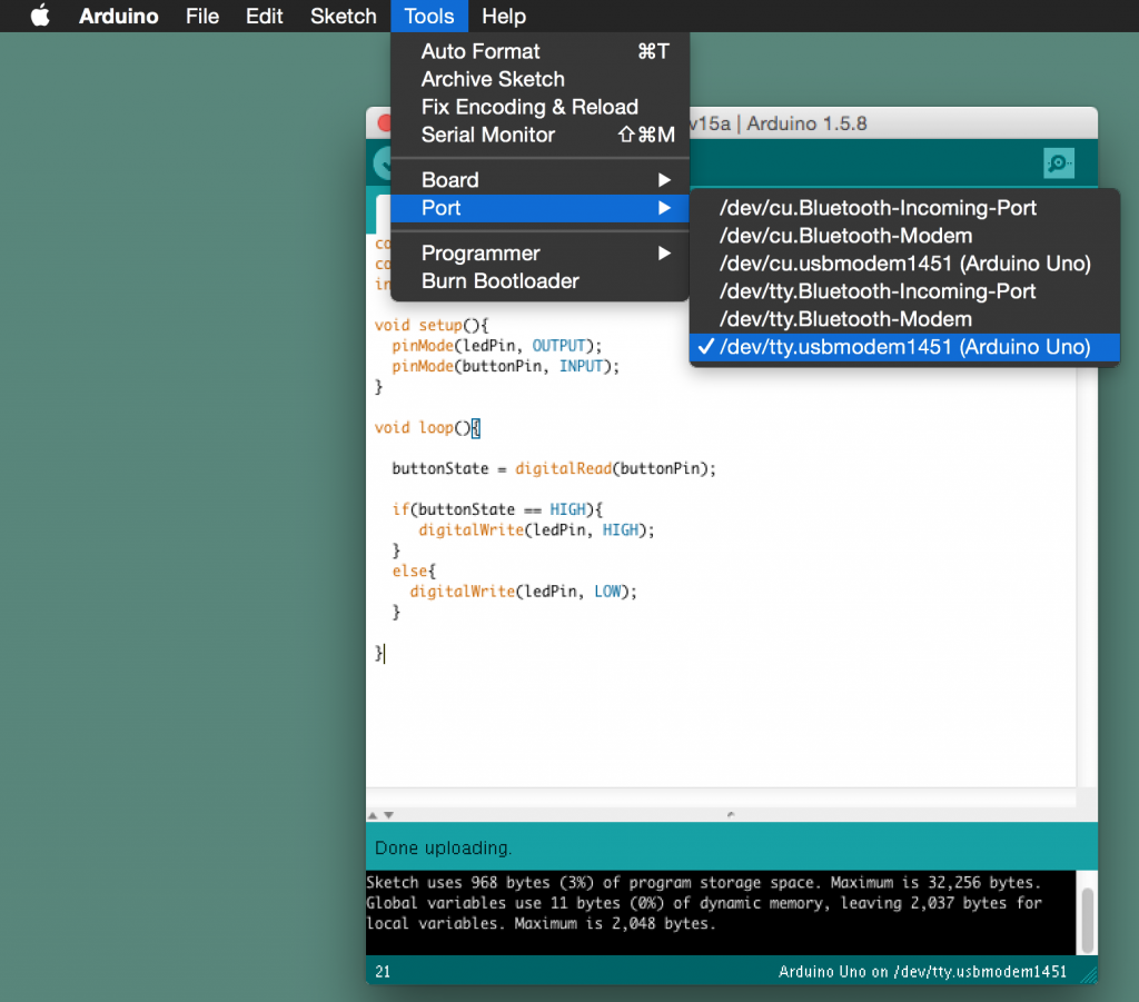
Selected the Arduino Uno the menu: Tools > Board > Arduino Uno

Select Uno

Then select the Arduino Port:

  • For Linux/windows Tools > Board > Comx where x is usually 3 or higher
  • For Mac Tools > Board > tty.usbmodemxxxx where xxxx is some number

Screen Shot 2014-11-16 at 7.01.13 PM

Then plug in the USB into your computer and Arduino and upload the code using the button as shown in the picture below

upload to Arduino

When the program is uploaded you are supposed to be able to press the the button which the program is continuously reading in the loop function and light the L.E.D. while the button is pressed….

BUT…… for me this was not the case, at least not completely. I found that when I put my hand anywhere near the circuit without actually touching the button the L.E.D. would still light up and sometimes the L.E.D. would just light up and stay on with out even touching the button as shown in the video below.

Frustrated yet? I was. So what to do when the instructions don’t work? Well for me usually I turn to stackoverflow for programming problems. So I had a look on the stackexchange which is the parent website of stack overflow and found an electronics subsection.

So I posted my issue, along with the steps I took myself to try and solve the problem (N.B.: if you go to any stack exchange and don’t show you made an effort, often you will be dismissed with comments like “have you even tried Googling it yourself”, So make the effort)

So here was my Question to the community

What I learned was that the reason the L.E.D was lighting when my hand was close to the circuit was due to ambient electromagnetic interference . As ‘Shubham’ explained to me

It’s because your button pin is floating (susceptible to ambient electromagnetic interference).

All the second resistor is doing is draining a little current from power to ground, when it should actually be functioning as the pull-down resistor for the button pin.To fix this issue I made the following change to the circuit:

I changed this:

Floating Button

To this:

Non Floating Button: Resistor acting as pull down resistor

And now the Circuit behaves as expected.

And there you go…a functional Arduino beginners project. I know some of you might be thinking “is it not a bit complex for simply turning on an L.E.D”. For that purpose yes, it is but imagine adding a few buttons, a few motors and a bit of work to the program, and it could turn into a basic remote controlled car. Or swap out the button for a light sensor and you could have an automated light that comes on when it gets dark. The possibilities are endless. But don’t worry, like you I’m a new to this too , so we can work on it together…

I based this post on a post I wrote for my own blog